Airless Sprayer Anatomy
An airless sprayer is made from several components which are made from many individual parts all working together to help make painting easier. Airless uses high pressure, rather than air, to atomize materials so they can be sprayed on to a surface. Here we will talk about the anatomy of an airless sprayer.
Pump / Fluid Section
The heart of an airless paint sprayer is the pump, also called the fluid section. It is what moves and pressurizes the material to be sprayed such as latex paint. Airless pumps are normally made of hardened, heavy-duty steel so they can create the high pressure needed to atomize paints and other “sprayable” materials.
Motor
Probably the second most important component is the motor, the power that drives the pump. Most airless paint sprayers use electric motors followed by gas engine driven sprayers. DP Xpro 63 Series electric paint sprayers come with a 2 years motor warranty.
Drive Train
The motor would be useless if it is not connected to the pump. Like a transmission, and axels in a car, the drive train in an airless gets the power to where it needs to go.
Hose
Next we need to get the pressurized liquid out of the sprayer and to the gun & spray tip. This is specially designed painting hose with high pressure the pump has put the fluid under.
Gun
For an airless to work the system needs to stay pressurized so we need to hold back the fluid until we need it. We also need to be able to easily and safely turn on and off the flow at will.
Tip
The spray tip controls both the spray-fan size and the amount of fluid that is allowed to come out. Because of this, it is a good idea to have several different tip sizes in your painting kit.
- Controls the amount of fluid being sprayed by using different orifice (opening) sizes.
- Orifice shape determines the spray pattern size – height and width
Pressure Control
Since we can’t control pressure with the gun, hose or tip, we need a pressure control. There are 2 main types of pressure controls; Electronic and Mechanical Pressure Control. The benefit of electronic pressure control is the less pressure drop (up and down) for example 20bar. but normally the mechanical regulator would cause more pressure gap like 40bar.
Chassis
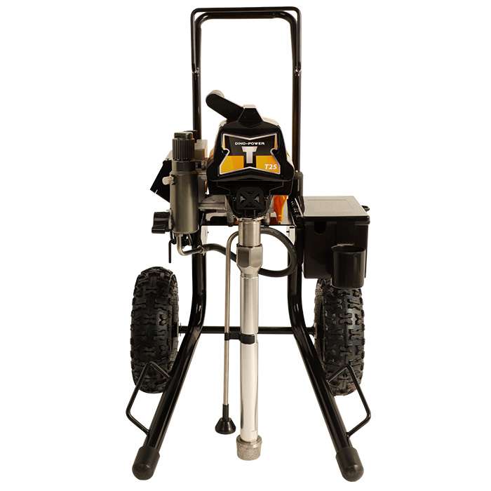
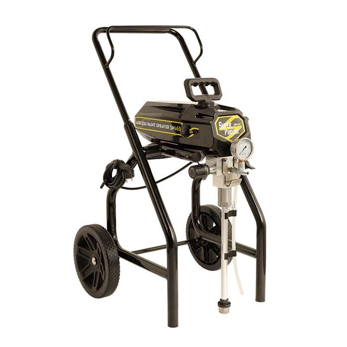
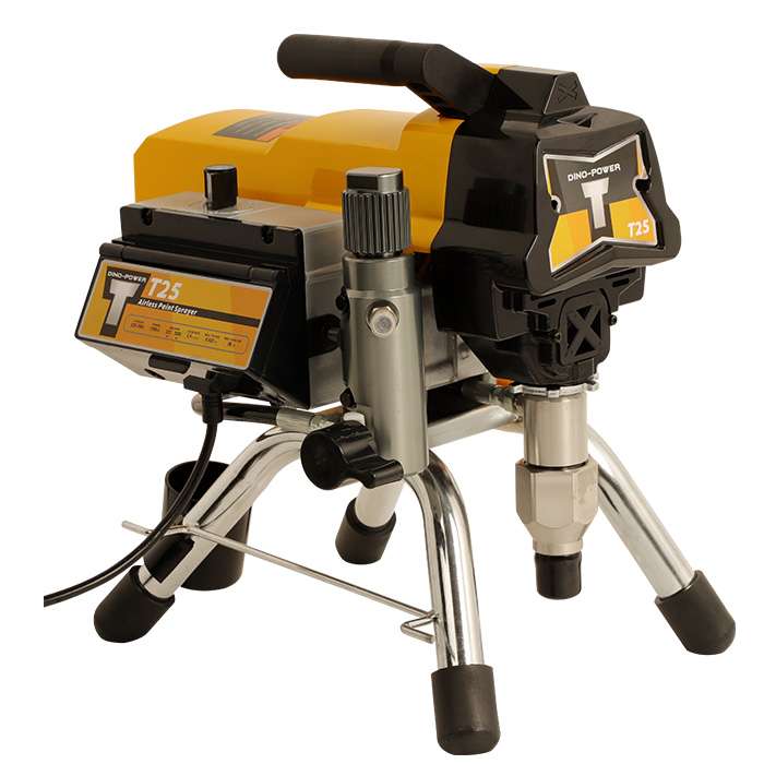
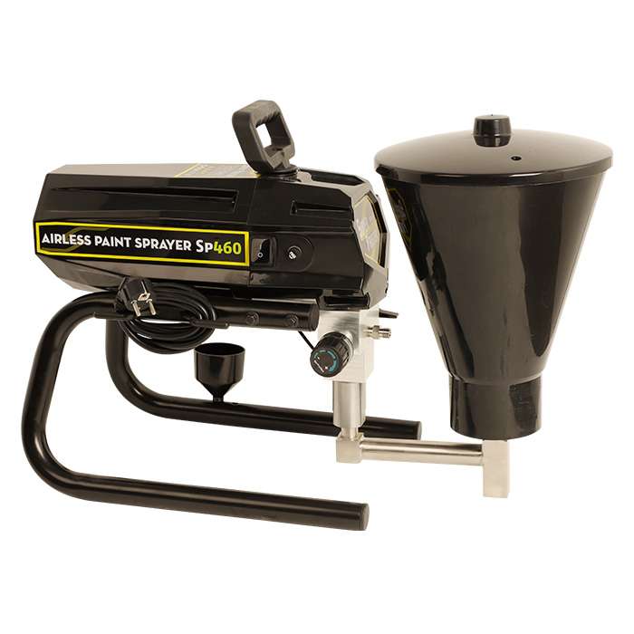
We need something to hold all these components together! There are three common chassis design configurations; Stand (also called a “skid”), Hi-Boy (sometimes called an “upright cart” or “High cart” “wheeled cart”) and Lo-Boy (sometimes called an “low-profile cart”). Some other airless parts that are within or in addition to main components you should be familiar with. But for the portable airless spray equipment, then it’s just hand carry type, easy to take and easy operation.
Prime / Spray Valve
The switch valve that sets the airless sprayer mode to either Prime Mode or Spray Mode.
Rod
The piston part of the fluid section.
Intake Tube
The tube that paint or other material to be sprayed is drawn into.
Return Tube
The tube that returns paint to the bucket during priming of the pump.
Manifold Filter
The filter within the sprayer which is the first line of defense against large particles in the paint.
Gun Filter
The filter inside the handle of the gun – the 2nd line of defense against remaining debris in the paint.
Packings
The seals in the fluid section which make the pump work.
Like people, airless paint sprayers come in many shapes and sizes.
Some of these design names are:
- Stand (Skid)
- Hi-Boy
- Low-Boy
motor-power 1500W
max-tip-size 0.023"
flow-rate 2.5L/min
Motor power 1000w
Max. tip size 0.021"
Flow rate 1.8L/min
motor-power 1500W
max-tip-size 0.023"
flow-rate 2.5L/min


